The Huawei CloudEngine S6730-H24X4Y4C is a next-generation enterprise-class switch designed to meet the demands of modern high-speed networks. It offers advanced features and robust performance, making it suitable for both core and aggregation layers in enterprise networks.
Key Features
The S6730-H24X4Y4C switch boasts several notable features:
▪ High Port Density: 24 x 10GE SFP+ ports, 4 x 25GE SFP28 ports, and 4 x 100GE QSFP28 ports.
▪ Advanced Security: Supports MACsec encryption for secure data transmission.
▪ VXLAN Support: Enables network virtualization for flexible and scalable network architectures.
▪ High Reliability: Features redundant power supplies and fans for enhanced system reliability.
▪ Comprehensive IPv6 Support: Fully compatible with IPv6, ensuring future-proof networking.
Technical Specifications
The S6730-H24X4Y4C switch comes with the following technical specifications:
Ports: 24 x 10GE SFP+ ports, 4 x 25GE SFP28 ports, 4 x 100GE QSFP28 ports.
Switching Capacity: 1.48 Tbps. Forwarding Performance: 1,100 Mpps.
MAC Address Table: Supports up to 288K MAC addresses.
Jumbo Frame Support: Up to 9,216 bytes. Power Supply: Dual pluggable power modules, supporting 1+1 redundancy.
Dimensions (H x W x D): 43.6 mm x 442.0 mm x 220.0 mm. Weight: Approximately 4.65 kg.
Advanced Security Features
Security is a paramount concern in modern networks. The S6730-H24X4Y4C addresses this with: MACsec Encryption: Ensures secure data transmission by providing point-to-point security on Ethernet links. Access Control Lists (ACLs): Offer granular traffic filtering to protect against unauthorized access and attacks. Storm Control: Prevents network disruptions caused by broadcast, multicast, or unknown unicast traffic storms.
High Availability and Reliability
To ensure continuous network operation, the S6730-H24X4Y4C is equipped with: Redundant Power Supplies: Dual hot-swappable power modules provide 1+1 redundancy, ensuring uninterrupted power. Hot-Swappable Fan Modules: Three built-in fans support forced air cooling, with airflow from the left side and front panel to the right side. Ethernet Ring Protection Switching (ERPS): Provides rapid network recovery in ring topologies, minimizing downtime.
Comprehensive IPv6 Support
As networks transition to IPv6, the S6730-H24X4Y4C ensures seamless integration with: Dual-Stack Architecture: Supports both IPv4 and IPv6 protocols, facilitating smooth migration. IPv6 Routing Protocols: Includes support for OSPFv3, BGP4+, and IS-ISv6 for dynamic routing in IPv6 networks. IPv6 ACLs: Provide traffic filtering capabilities for IPv6 traffic, enhancing security.
Energy Efficiency
The S6730-H24X4Y4C is designed with energy efficiency in mind: Energy-Efficient Ethernet (EEE): Reduces power consumption during periods of low network activity. Intelligent Fan Speed Adjustment: Automatically adjusts fan speed based on temperature, reducing energy usage and noise.
Management and Maintenance
Efficient network management is facilitated through: Command-Line Interface (CLI): Provides a familiar interface for network administrators to configure and monitor the switch. Simple Network Management Protocol (SNMP): Allows for centralized management and monitoring of network devices. Remote Monitoring (RMON): Offers proactive network monitoring and troubleshooting capabilities.
Application Scenarios
The versatility of the S6730-H24X4Y4C makes it suitable for various deployment scenarios: Enterprise Campus Networks: Serves as a core or aggregation switch, providing high-speed connectivity and advanced features. Data Center Top-of-Rack (ToR): Offers high-density 10GE and 25GE ports for server connectivity, with 100GE uplinks to the aggregation layer. Metropolitan Area Networks (MANs): Functions as an aggregation switch, supporting high-bandwidth services and advanced QoS features.
Conclusion
The Huawei CloudEngine S6730-H24X4Y4C is a powerful and versatile switch designed to meet the demands of modern enterprise networks.
Huawei CloudEngine S6730-H24X4Y4C Switches
Huawei All Series Switches New and Used
For Cisco product list and quote, please visit: https://www.hi-network.com/categories/cisco or contact us at www.hi-network.com (Email: [email protected])
S6730-H24X4Y4C (02353NRD) Overview
Table 4-200 Basic information about the S6730-H24X4Y4C
| Item | Details |
|---|---|
| Description | S6730-H24X4Y4C (24*10GE SFP+ ports, 4*25GE SFP28 ports, 4*100GE QSFP28 ports, without power module) |
| Part Number | 02353NRD |
| Model | S6730-H24X4Y4C |
| First supported version | V200R020C00 |
Components
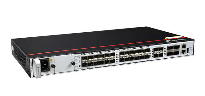
Figure 4-85 S6730-H24X4Y4C appearance

| 1 | NOTE: | 2 | NOTE: |
| 3 | NOTE: | 4 | Four 1GE/10GE/25GE SFP28 optical ports |
| 5 | Four 40GE/100GE QSFP28 optical ports | 6 | One console port |
| 7 | One ETH management port | 8 | One USB port |
| 9 | NOTICE: | - | NOTE: |
Ports
Table 4-201 Ports on the S6730-H24X4Y4C
| Port | Connector Type | Description | Available Components |
|---|---|---|---|
| 10GE SFP+ optical port | SFP+ | A 10GE SFP+ Ethernet optical port supports auto-sensing to 1000 Mbit/s. It sends and receives service data at 1000 Mbit/s or 10 Gbit/s.In V200R021C00 and later versions, a RTU license can be loaded to increase the port rate to 25 Gbit/s. | GE eSFP optical modulesGE-CWDM eSFP optical modulesGE-DWDM eSFP optical modulesGE SFP copper module10GE SFP+ optical modules (OSXD22N00 and SFP-10G-ZR not supported)10GE SFP+ copper module (supported in V200R023C10 and later versions)1 m, 2 m, 3 m, 5 m, and 10 m SFP+ high-speed copper cables3 m and 10 m SFP+ AOC cables0.5 m and 1.5 m SFP+ dedicated stack cables (supported by the last 16 SFP+ ports and used only for zero-configuration stacking)25GE SFP28 optical modules (need a license loaded)1 m SFP28 high-speed copper cable (need a license loaded)3 m, 5 m, 7 m, and 10 m SFP28 AOC cables (need a license loaded) |
| 1GE/10GE/25GE SFP28 optical port | SFP28 | A 1GE/10GE/25GE SFP28 optical port sends and receives service data at 1 Gbit/s, 10 Gbit/s, or 25 Gbit/s.When a 25GE optical module is connected to a port, the port can automatically adjust its rate to 25 Gbit/s.When a 10GE optical module is connected to a port, the port can automatically adjust its rate to 10 Gbit/s.Before installing a GE optical module or GE copper module on a port, run the port mode ge command to configure the port to work at 1 Gbit/s. | GE eSFP optical modulesGE-CWDM eSFP optical modulesGE-DWDM eSFP optical modulesGE SFP copper module10GE SFP+ optical modules (OSXD22N00 and SFP-10G-ZR not supported)10GE SFP+ copper module (supported in V200R023C10 and later versions)25GE SFP28 optical modules1 m, 2 m, 3 m, 5 m, and 10 m SFP+ high-speed copper cables3 m and 10 m SFP+ AOC cables1 m SFP28 high-speed copper cable3 m, 5 m, 7 m, and 10 m SFP28 AOC cables |
| 40GE/100GE QSFP28 optical port | QSFP28 | A 40GE/100GE QSFP28 optical port sends and receives service traffic at 40 Gbit/s or 100 Gbit/s.A QSFP28 optical port cannot be split into four 10GE ports, regardless of whether the port uses a QSFP28 or QSFP+ optical module. | 40GE QSFP+ optical modules100GE QSFP28 optical modules1 m, 3 m, and 5 m QSFP+ to QSFP+ high-speed copper cables10 m QSFP+ to QSFP+ AOC cable1 m QSFP28 to QSFP28 high-speed copper cable10 m QSFP28 to QSFP28 AOC cable2 m QSFP28 dedicated stack cable (supported in V200R020C10 and later versions) |
| Console port | RJ45 | The console port is connected to a console for on-site configuration. | Console cable |
| ETH management port | RJ45 | You can connect a switch to a configuration terminal or network management workstation through the ETH management port to configure the switch locally or remotely.You can choose to download the software package through the ETH management port in the BootLoad menu. File transfer through the ETH management port is faster than transfer through the console port. | Ethernet cable |
| USB port | USB 2.0 Type A | The USB port can have a USB flash drive connected to upgrade the switch, or transfer configuration files or other files. The USB port can only connect to a USB flash drive that complies with USB 2.0.USB flash drives from different vendors differ in model compatibility and drivers. If a USB flash drive cannot be used, try to replace it with another one from a mainstream vendor. Switches support a maximum of 128 GB USB flash drives. | USB flash drive |
Indicators and Buttons
Figure 4-86 Indicators on the switch
| No. | Indicator | Name | Color | Status | Description |
|---|---|---|---|---|---|
| 1 | PWR1 | Power module indicator | - | Off | No power module is available in power module slot 1, or the switch has only one power module but the power module does not work normally. |
| Green | Steady on | A power module is installed in power module slot 1 and is working normally. | |||
| Yellow | Steady on | The switch has two power modules installed. Any of the following situations occurs in power module slot 1:A power module is available in this slot but it is not connected to a power source.The power module in this slot has failed. | |||
| 2 | PWR2 | Power module indicator | - | Off | No power module is available in power module slot 2, or the switch has only one power module but the power module does not work normally. |
| Green | Steady on | A power module is installed in power module slot 2 and is working normally. | |||
| Yellow | Steady on | The switch has two power modules installed. Any of the following situations occurs in power module slot 2:A power module is available in this slot but it is not connected to a power source.The power module in this slot has failed. | |||
| 3 | SYS | System status indicator | - | Off | The system is not running. |
| Green | Fast blinking | The system is starting. | |||
| Green | Steady on | During the system startup preparation phase, the SYS indicator is steady green, which lasts for a maximum of 30 seconds. | |||
| Green | Slow blinking | The system is running normally. | |||
| Red | Steady on | The system does not work normally after registration, or a fan alarm or a temperature alarm has been generated. | |||
| 4 | MST | Stack indicator | - | Off | If you are not changing the indicator mode (default): The switch is a standby or slave switch in a stack or the stacking function is not enabled on the switch.If you are changing the indicator mode: The stack mode is not selected. |
| Green | Steady on | The stack mode is selected. The switch is a standby or slave switch in a stack, and the service port indicators show the stack ID of the switch. | |||
| Green | Blinking | If you are not changing the indicator mode (default): The switch is the master switch in a stack or a standalone switch with the stacking function enabled.If you are changing the indicator mode: The stack mode is selected. The switch is the master switch in a stack or a standalone switch, and the service port indicators show the stack ID of the master switch. After 45 seconds, the service port indicators automatically restore to the status mode. | |||
| 5 | SPEED | Speed indicator | - | Off | The speed mode is not selected. |
| Green | Steady on | The speed mode is selected, and service port indicators show the speed of each port. | |||
| 6 | MODE | Mode switch button | - | - | NOTE:Hold down the mode switch button for 6s and release it to start the web initial login mode. Either of the following situations will occur: |
| 7 | - | Optical service port indicator (two indicators for each port) | Each optical port has two single-color indicators. The one on the left is the ACT indicator (yellow), and the one on the right is the LINK indicator (green).Arrowheads show the positions of ports. A down arrowhead indicates a port at the bottom, and an up arrowhead indicates a port at the top. | Meanings of service port indicators vary in different modes. For details, see Table 4-203 and Table 4-204. | |
| 8 | - | Optical service port indicator (one indicator for each port) | Each optical port has one single-color indicator. Arrowheads show the positions of ports. | ||
| 9 | ID | ID indicator | - | Off | The ID indicator is not used (default state). |
| Blue | Steady on | The indicator identifies the switch to maintain. The ID indicator can be turned on or off remotely to help field engineers find the switch to maintain. | |||
| 10 | L/A | ETH port indicator | - | Off | The ETH port is not connected. |
| Green | Steady on | The ETH port is connected. | |||
| Green | Blinking | The ETH port is sending or receiving data. | |||
| 11 | USB | USB-based deployment indicator | - | Off | No USB flash drive is connected to the switch.The USB port is damaged.The indicator is damaged.The USB flash drive does not have any configuration file and cannot be used for deployment.The switch has been upgraded using the USB flash drive and is restarting. |
| Green | Steady on | A USB-based deployment has been completed. | |||
| Green | Blinking | The system is reading data from a USB flash drive. | |||
| Yellow | Steady on | The switch has copied all the required files and completed the file check. The USB flash drive can be removed from the switch. | |||
| Red | Blinking | An error has occurred when the system is executing the configuration file or reading data from the USB flash drive. | |||
Table 4-203 Description of service port indicators in different modes (two indicators for each port)
| Display Mode | Color | Status | Description |
|---|---|---|---|
| Default mode (LINK indicator) | - | Off | The port is not connected or has been shut down. |
| Green | Steady on | A link has been established on the port. | |
| Default mode (ACT indicator) | - | Off | The port is not connected or has been shut down, or no data is transmitted or received. |
| Yellow | Blinking | The port is sending or receiving data. | |
| MST stack mode (LINK and ACT indicators) | - | Off | Port indicators do not show the stack ID of the switch. |
| Green and yellow | Steady on simultaneously | The switch is not the master switch in a stack. | |
| Green and yellow | Blinking simultaneously | The switch is the master switch in a stack. | |
| Speed mode (LINK indicator) | - | Off | The port is not connected or has been shut down. |
| Green | Steady on | GE/10GE SFP+ port: The port is operating at 1 Gbit/s.1GE/10GE/25GE SFP28 port: The port is operating at 1 Gbit/s or 10 Gbit/s. | |
| Green | Blinking | GE/10GE SFP+ port: The port is operating at 10 Gbit/s.1GE/10GE/25GE SFP28 port: The port is operating at 25 Gbit/s. |
Table 4-204 Description of service port indicators in different modes (one indicator for each port)
| Display Mode | Color | Status | Description |
|---|---|---|---|
| Default mode | - | Off | The port is not connected or has been shut down. |
| Green | Steady on | A link has been established on the port. | |
| Green | Blinking | The port is sending or receiving data. | |
| Speed mode | - | Off | The port is not connected or has been shut down. |
| Green | Steady on | 1GE/10GE/25GE SFP28 port: The port is operating at 1 Gbit/s or 10 Gbit/s.40GE/100GE QSFP28 port: The port is operating at 40 Gbit/s. | |
| Green | Blinking | 1GE/10GE/25GE SFP28 port: The port is operating at 25 Gbit/s.40GE/100GE QSFP28 port: The port is operating at 100 Gbit/s. |
Power Supply System
The switch can use a single power module or two power modules for 1+1 power redundancy. Pluggable AC and DC power modules can be used together in the same switch.
Heat Dissipation System
The switch has three built-in fans for forced air cooling. Air flows in from the left side and front panel, and exhausts from the right side.


This figure only shows the airflow direction and does not depict the actual device.
Technical Specifications
Table 4-205 Technical specifications of the S6730-H24X4Y4C
| Item | Specification |
|---|---|
| Dimensions without packaging (H x W x D) [mm(in.)] | Basic dimensions (excluding the parts protruding from the body): 43.6 mm x 442.0 mm x 220.0 mm (1.72 in. x 17.4 in. x 8.66 in.)Maximum dimensions (the depth is the distance from ports on the front panel to the parts protruding from the rear panel): 43.6 mm x 442.0 mm x 231.0 mm (1.72 in. x 17.40 in. x 9.09 in.) |
| Dimensions with packaging (H x W x D) [mm(in.)] | 115.0 mm x 545.0 mm x 360.0 mm (4.53 in. x 21.46 in. x 14.17 in.) |
| Chassis height [U] | 1 U |
| Chassis material | Metal |
| Weight without packaging [kg(lb)] | 3.4 kg (7.5 lb) |
| Weight with packaging [kg(lb)] | 4.65 kg (10.25 lb) |
| Typical power consumption [W] | 186 W |
| Typical heat dissipation [BTU/hour] | 634.65 BTU/hour |
| Maximum power consumption [W] | 253 W |
| Maximum heat dissipation [BTU/hour] | 863.26 BTU/hour |
| Static power consumption [W] | 116 W |
| MTBF [years] | 54.68 years |
| MTTR [hours] | 2 hours |
| Availability | > 0.99999 |
| Noise at normal temperature (acoustic power) [dB(A)] | 64.5 dB(A) |
| Noise at normal temperature (acoustic pressure) [dB(A)] | 51.7 dB(A) |
| Number of card slots | 0 |
| Number of power slots | 2 |
| Number of fans modules | 3 |
| Redundant power supply | 1+1Pluggable AC and DC power modules can be used together in the same switch. |
| Long-term operating temperature [°C(°F)] | -5°C to +45°C (23°F to 113°F) at an altitude of 0-1800 m (0-5906 ft.) |
| Restriction on the operating temperature variation rate [°C(°F)] | When the altitude is 1800–5000 m (5906–16404 ft.), the highest operating temperature reduces by 1°C (1.8°F) every time the altitude increases by 220 m (722 ft.).The device cannot start when the temperature is lower than 0°C (32°F).When the QSFP-100G-ER4 or QSFP-100G-LR1 optical module is used, the operating temperature ranges from -5°C to +40°C (23°F to 104°F). |
| Storage temperature [°C(°F)] | -40°C to +70°C (-40°F to +158°F) |
| Long-term operating relative humidity [RH] | 5% to 95%, noncondensing |
| Long-term operating altitude [m(ft.)] | 0-5000 m (0-16404 ft.) |
| Storage altitude [m(ft.)] | 0-5000 m (0-16404 ft.) |
| Power supply mode | Pluggable power supply |
| Rated input voltage [V] | AC input: 100 V AC to 240 V AC; 50/60 HzHigh-voltage DC input: 240 V DCDC input: –48 V DC to –60 V DC |
| Input voltage range [V] | AC input: 90–290 V AC; 45–65 HzHigh-voltage DC input: 190 V DC to 290 V DCDC input: -38.4 V DC to -72 V DC |
| Maximum input current [A] | The current specifications depend on the pluggable power modules in use. For details, see the related power module specifications. |
| Memory | 4 GB |
| Flash memory | 2 GB in total. To view the available flash memory size, run the display version command. |
| Console port | RJ45 |
| Eth Management port | RJ45 |
| USB | Supported |
| RTC | Supported |
| RPS input | Not supported |
| Service port surge protection [kV] | - |
| Power supply surge protection [kV] | AC power module configured: ±6 kV in differential mode, ±6 kV in common modeDC power module configured: ±2 kV in differential mode, ±4 kV in common mode |
| Ingress protection level (dustproof/waterproof) | IP20 |
| Types of fans | Built-in |
| Heat dissipation mode | Heat dissipation with fan, intelligent fan speed adjustment |
| Airflow direction | Air intake from left and front, air exhaustion from right |
| PoE | Not supported |
| Certification | EMC certificationSafety certificationManufacturing certification |