Introduction
The CloudEngine S5735-L24P4XE-A-V2 is an enterprise-class access switch designed for campus and office networks. It delivers stable performance, PoE support, and intelligent management, making it suitable for digital workplaces and small to medium-sized enterprises. With flexible deployment and energy-efficient operation, it helps simplify network construction and daily maintenance.
Product Highlights
▪ Ports: 24 x GE Ethernet access ports
▪ PoE Support: PoE+ for IP phones and wireless APs
▪ Uplink Ports: 4 x 10GE SFP+ uplinks
▪ Security Features: User authentication and attack defense
Overall, the CloudEngine S5735-L24P4XE-A-V2 provides reliable access-layer switching with strong security and intelligent O&M capabilities.
Download Datasheet: S5735-L24P4XE-A-V2 (98012026 98012026-001) Datasheet.pdf
For more datasheets, please go to the Download tab on each product details page, or search in the Datasheet Download Center.
S5735-L24P4XE-A-V2 (98012026-001)
Overview
Table 4-326 Basic information about the S5735-L24P4XE-A-V2
| Item | Details |
|---|---|
| Description | S5735-L24P4XE-A-V2 (24*10/100/1000BASE-T ports, 4*10GE SFP+ ports, 2*12GE stack ports, PoE+, AC power, Specially protected models) |
| Part Number | 98012026-001 |
| Model | S5735-L24P4XE-A-V2 |
| First supported version | V600R022C01 |
Components
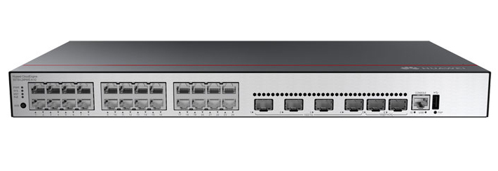
Figure 4-113 S5735-L24P4XE-A-V2 appearance

| 1 | One MODE button | 2 | Twenty-four 10/100/1000BASE-T PoE+ ports |
| 3 | Four 10GE SFP+ ports | 4 | Two stack ports |
| 5 | One console port | 6 | One USB port |
| 7 | One PNP buttonNOTICE:To restore the factory settings and reset the switch, hold down the button for at least 6 seconds.To reset the switch, press the button.Resetting the switch will cause service interruption. Exercise caution when you press the PNP button. | 8 | Ground screwNOTE:It is used with a ground cable. |
| 9 | Jack for AC power cable locking strapNOTE:The AC power cable locking strap is not delivered with the switch. | 10 | AC socketNOTE:It is used with an AC power cable. |
Ports
Table 4-327 Ports on the S5735-L24P4XE-A-V2
| Port | Connector Type | Description | Available Components |
|---|---|---|---|
| 10/100/1000BASE-T port | RJ45 | A 10/100/1000BASE-T Ethernet electrical port sends and receives service data at 10/100/1000 Mbit/s. | Ethernet cable |
| 10GE SFP+ optical port | SFP+ | A 10GE SFP+ Ethernet optical port supports auto-sensing to 1000 Mbit/s. It sends and receives service data at 1000 Mbit/s or 10 Gbit/s. | GE eSFP optical modulesGE-CWDM eSFP optical modulesGE-DWDM eSFP optical modulesGE SFP copper modules10GE SFP+ optical modules10GE-CWDM SFP+ optical modules10GE-DWDM SFP+ optical modules10GE SFP+ copper modules (V600R024C00 and later versions)PEN remote optical modules (V600R024C00 and later versions)1 m and 3 m SFP+ high-speed copper cables (only used for stack connection in versions earlier than V600R023C00)10 m SFP+ AOC cables0.5 m and 1.5 m SFP+ dedicated stack cables (only used for stack connection; zero-configuration stacking supported from V600R023C00) |
| Stack port | SFP+ | A stack port connects multiple switches through stack cables to virtualize them into one switch logically. It is used only in stacking scenarios and does not need to be configured. In a stack, the working rate of a single port is increased to 12 Gbit/s by default. | 1 m SFP+ high-speed copper cables0.5 m and 1.5 m SFP+ dedicated stack cables |
| Console port | RJ45 | The console port is connected to a console for on-site configuration. | Console cable |
| USB port | USB 2.0 Type A | The USB port can have a USB flash drive connected to upgrade the switch, or transfer configuration files or other files. The USB port can only connect to a USB flash drive that complies with USB 2.0.USB flash drives from different vendors differ in model compatibility and drivers. If a USB flash drive cannot be used, try to replace it with another one from a mainstream vendor. | USB flash drive |
Indicators and Buttons
Figure 4-114 Indicators on the Switch

Table 4-328 Description of indicators on the switch
| No. | Indicator | Name | Color | Status | Description |
|---|---|---|---|---|---|
| 1 | PWR | Power module indicator | - | Off | The switch is powered off. |
| Green | Steady on | The power supply is normal. | |||
| Yellow | Steady on | The power supply is abnormal. | |||
| 2 | SYS | System status indicator | - | Off | The system is not running. |
| Green | Fast blinking | The system is starting. | |||
| Green | Steady on | During the system startup preparation phase, the SYS indicator is steady green, which lasts for a maximum of 30 seconds. | |||
| Green | Slow blinking | The system is running normally. | |||
| Red | Steady on | The system does not work normally after registration, or a fan alarm or a temperature alarm has been generated. | |||
| 3 | MST | Stack indicator | - | Off | If you are not changing the indicator mode (default): The switch is a standby or slave switch in a stack or the stacking function is not enabled on the switch.If you are changing the indicator mode: The stack mode is not selected. |
| Green | Steady on | The stack mode is selected. The switch is a standby or slave switch in a stack, and the service port indicators show the stack ID of the switch. | |||
| Green | Blinking | If you are not changing the indicator mode (default): The switch is the master switch in a stack or a standalone switch with the stacking function enabled.If you are changing the indicator mode: The stack mode is selected. The switch is the master switch in a stack or a standalone switch, and the service port indicators show the stack ID of the master switch. After 45 seconds, the service port indicators automatically restore to the status mode. | |||
| 4 | PoE | PoE indicator | - | Off | The PoE mode is not selected. |
| Green | Steady on | The PoE mode is selected, and service port indicators show the PoE status of each port. | |||
| 5 | MODE | Mode switch button | - | - | When you press this button once, the service port indicators change to the stack mode and show the stack ID of the local switch.When you press this button a second time, the service port indicators change to the PoE mode and show the PoE status of each service port.When you press this button a third time, the service port indicators restore to the default mode and show the connection status and link activity of each service port.If you do not press the MODE button within 45 seconds, the service port indicators restore to the default mode. In this case, the PoE indicator is off.NOTE:In V600R023C00 and later versions, hold down the mode switch button for 6s and release it to start the web initial login mode. Either of the following situations will occur:If the switch has no configuration file, the system attempts to enter the web initial login mode.If the system enters the web initial login mode successfully, the MST mode indicator turns green and stays on for a maximum of 45 seconds.If the login fails, check whether the device uses factory default settings. |
| 6 | - | Service port indicator (one indicator for each port) | Arrowheads show the positions of ports. A down arrowhead indicates a port at the bottom, and an up arrowhead indicates a port at the top. | Meanings of service port indicators vary in different modes. For details, see Table 4-329.NOTE:If a power failure occurs on a device's PCB board, indicators of the last four GE, 10GE, or 25GE optical ports on the device's front panel blink green cyclically at an interval of 1 second, with each indicator illuminating for 0.25 seconds. | |
| 7 | ID | ID indicator | - | Off | The ID indicator is not used (default state). |
| Blue | Steady on | The indicator identifies the switch to maintain. The ID indicator can be turned on or off remotely to help field engineers find the switch to maintain. | |||
| 8 | USB | USB-based deployment indicator | - | Off | No USB flash drive is installed, or the indicator fails. |
| Green | Steady on | USB-based deployment succeeds. If there is no deployment configuration file, deployment will be repeatedly performed. In this case, the indicator is also steady green. | |||
| Green | Blinking | USB-based deployment is in progress. | |||
| Red | Steady on | USB-based deployment fails. | |||
| Display Mode | Color | Status | Description |
|---|---|---|---|
| Default mode | - | Off | The port is not connected or has been shut down. |
| Green | Steady on | A link has been established on the port. | |
| Green | Blinking | The port is sending or receiving data. | |
| MST stack mode | - | Off | Port indicators do not show the stack ID of the switch. |
| Green | Steady on | The switch is not the master switch in a stack.If the indicator of a port is steady on, the number of this port is the stack ID of the switch. | |
| Green | Blinking | The switch is the master switch in a stack.If the indicator of a port is blinking, the number of this port is the stack ID of the switch. | |
| PoE mode | - | Off | The port is not providing power to a powered device (PD). |
| Green | Steady on | The port is providing power to a PD. | |
| Green | Blinking | The power of the PD connected to the port exceeds the power capacity of the port or the power threshold configured on the port. Alternatively, the PD does not comply with IEEE standards. | |
| Speed modeNOTE:In V600R023C00 and later versions, the service port indicators can be set to the speed mode through the set device led mode Speed diagnostic command.The default mode is automatically restored after 45s. | - | Off | The port is not connected or has been shut down. |
| Green | Steady on | 10/100/1000BASE-T port: The port is operating at 10 Mbit/s or 100 Mbit/s.1GE/10GE SFP+ port: The port is operating at 1 Gbit/s. | |
| Green | Blinking | 10/100/1000BASE-T port: The port is operating at 1000 Mbit/s.1GE/10GE SFP+ port: The port is operating at 10 Gbit/s.1000BASE-X port: The port is operating at 1000 Mbit/s. |
Power Supply System
The switch has a built-in AC power module and does not support pluggable power modules. The built-in power module can provide 400 W PoE power, which ensures full PoE power on 24 ports in compliance with 802.3af or on 13 ports in compliance with 802.3at.
Heat Dissipation System
The switch has two built-in fans for forced air cooling. Air flows in from the left side and front panel, and exhausts from the right side.
When working properly at a normal temperature, the device meets the desktop-class noise requirements. However, the fan speed may be high and the noise may be loud during device startup.


This figure only shows the airflow direction and does not depict the actual device.
Technical Specifications
Table 4-330 Technical specifications of the S5735-L24P4XE-A-V2
| Item | Specification |
|---|---|
| Dimensions without packaging (H x W x D) [mm(in.)] | Basic dimensions (excluding the parts protruding from the body): 43.6 mm x 442.0 mm x 220.0 mm (1.72 in. x 17.4 in. x 8.66 in.)Maximum dimensions (the depth is the distance from ports on the front panel to the parts protruding from the rear panel): 43.6 mm x 442.0 mm x 227.0 mm (1.72 in. x 17.4 in. x 8.94 in.) |
| Dimensions with packaging (H x W x D) [mm(in.)] | 90.0 mm x 550.0 mm x 360.0 mm (3.54 in. x 21.65 in. x 14.17 in.) |
| Chassis height [U] | 1 U |
| Chassis material | Metal |
| Weight without packaging [kg(lb)] | 2.94 kg (6.48 lb) |
| Weight with packaging [kg(lb)] | 3.81 kg (8.4 lb) |
| Typical power consumption [W] | 39.84 W |
| Typical heat dissipation [BTU/hour] | 135.94 BTU/hour |
| Maximum power consumption [W] | Without PoE: 55.40 WFull PoE load: 496.08 W (PoE: 400 W) |
| Maximum heat dissipation [BTU/hour] | Without PoE: 189.03Full PoE load: 1692.67 |
| Static power consumption [W] | 29.17 W |
| MTBF [years] | 60.40 years |
| Availability | > 0.99999 |
| Noise at normal temperature (acoustic power) [dB(A)] | 49.3 dB(A) |
| Noise at normal temperature (acoustic pressure) [dB(A)] | 37.3 dB(A) |
| Number of card slots | 0 |
| Number of power slots | 0 |
| Number of fans modules | 2 |
| Redundant power supply | Not supported |
| Long-term operating temperature [°C(°F)] | -5°C to +50°C (23°F to 122°F) at an altitude of 0-1800 m (0-5905.44 ft.) |
| Restriction on the operating temperature variation rate [°C(°F)] | When the altitude is 1800–5000 m (5906–16404 ft.), the highest operating temperature reduces by 1°C (1.8°F) every time the altitude increases by 220 m (722 ft.).Devices cannot start when the temperature is lower than 0°C (32°F). |
| Storage temperature [°C(°F)] | –40°C to +70°C (–40°F to +158°F) |
| Long-term operating relative humidity [RH] | 5% RH to 95% RH, non-condensing |
| Long-term operating altitude [m(ft.)] | 0–5000 m (0–16404 ft.) |
| Storage altitude [m(ft.)] | 0-5000 m (0-16404 ft.) |
| Power supply mode | AC built-in |
| Rated input voltage [V] | AC input: 100 V AC to 240 V AC, 50/60 HzHigh-voltage DC input: 240 V DC |
| Input voltage range [V] | AC input: 90 V AC to 290 V AC; 45 Hz to 65 HzHigh-voltage DC input: 190 V DC to 290 V DC |
| Maximum input current [A] | 6 A |
| Memory | 2 GB |
| Flash memory | Physical space: 1 GB |
| Console port | RJ45 |
| Eth Management port | Not supported |
| USB | Supported |
| RTC | Not supported |
| RPS input | Not supported |
| Power supply surge protection [kV] | Differential mode: ±6 kV; common mode: ±6 kV |
| Ingress protection level (dustproof/waterproof) | IP20 |
| Types of fans | Built-in |
| Heat dissipation mode | Air cooling for heat dissipation, intelligent fan speed adjustment |
| Airflow direction | Air intake from left and front, air exhaustion from right |
| PoE | Supported |
| Certification | EMC certificationSafety certificationManufacturing certification |