The S5735-L8P4X-IA1 is a robust, industrial-grade Ethernet switch developed by Huawei, designed to meet the demanding requirements of modern enterprise and industrial networks. With advanced features, high reliability, and flexible deployment capabilities, this switch is ideal for environments such as transportation, energy, manufacturing, and smart city infrastructure.
This article explores the key features, technical specifications, architecture, performance, and practical applications of the S5735-L8P4X-IA1, offering a complete understanding of its value in modern networking solutions.
Overview of S5735-L8P4X-IA1
The S5735-L8P4X-IA1 belongs to Huawei’s S5735 series of switches, which are known for their industrial-grade durability and high-performance Layer 3 capabilities. This model is specifically designed to operate in harsh environments, supporting extended temperature ranges and offering enhanced protection against dust, vibration, and electromagnetic interference.
It combines powerful switching capabilities with advanced routing features, making it suitable for both enterprise campus networks and industrial deployments.
Key Characteristics
The switch stands out due to its compact design, fanless operation, and high port density relative to its size. It is optimized for edge deployments where space and reliability are critical.
Key Technical Specifications
The S5735-L8P4X-IA1 offers a balanced combination of performance, scalability, and reliability. Below are its primary technical specifications:
▪ Ports: 8 x 1GbE PoE+ ports, 4 x 10GbE SFP+ uplink ports
▪ Switching Capacity: High-performance switching fabric for enterprise-level traffic handling
▪ Forwarding Rate: Wire-speed forwarding for all ports
▪ Power Supply: Industrial-grade power input with redundancy support
▪ Operating Temperature: Wide temperature range suitable for harsh environments
▪ Cooling System: Fanless design for silent and reliable operation
▪ Layer Support: Advanced Layer 2 and Layer 3 features
▪ PoE Capability: Supports Power over Ethernet for connected devices
▪ Protection Level: Industrial-grade protection against dust and vibration
Hardware Design and Build Quality
The S5735-L8P4X-IA1 is engineered for durability and long-term reliability. Its rugged metal enclosure ensures resistance to physical stress and environmental hazards. The fanless design eliminates moving parts, reducing the risk of mechanical failure and minimizing maintenance requirements.
This switch is particularly suitable for installation in control cabinets, roadside units, and factory floors where traditional networking equipment may not perform reliably.
Compact and Efficient Form Factor
The compact size allows for flexible deployment in space-constrained environments. Despite its small footprint, it provides high port density and powerful performance, making it a versatile solution for edge networking scenarios.
Performance and Switching Capabilities
Performance is a critical factor in industrial networking, and the S5735-L8P4X-IA1 excels in this area. It supports high-speed data transmission with minimal latency, ensuring smooth operation of mission-critical applications.
The inclusion of 10GbE uplink ports enables high-bandwidth connectivity to aggregation or core layers, reducing bottlenecks and improving overall network efficiency.
Wire-Speed Forwarding
The switch supports wire-speed forwarding across all ports, ensuring that data packets are transmitted without delay. This is particularly important for real-time applications such as video surveillance, industrial automation, and smart transportation systems.
High Switching Capacity
Its high switching capacity ensures that the device can handle large volumes of traffic without performance degradation, even during peak usage periods.
Layer 2 and Layer 3 Features
The S5735-L8P4X-IA1 offers a comprehensive set of Layer 2 and Layer 3 features, enabling flexible network design and efficient traffic management.
Layer 2 Capabilities
The switch supports essential Layer 2 functions such as VLANs, MAC address learning, spanning tree protocols, and link aggregation. These features ensure efficient traffic segmentation and redundancy.
Layer 3 Routing
Advanced Layer 3 features, including static routing and dynamic routing protocols, allow the switch to function as a routing device in small to medium-sized networks. This reduces the need for additional routing hardware and simplifies network architecture.
Power over Ethernet (PoE) Functionality
The S5735-L8P4X-IA1 supports PoE+, enabling it to deliver both data and power over a single Ethernet cable. This feature is particularly useful for powering devices such as IP cameras, wireless access points, and IoT sensors.
Efficient Power Distribution
The switch intelligently manages power allocation to connected devices, ensuring optimal performance and preventing overload. This reduces the need for separate power supplies and simplifies installation.
Industrial-Grade Reliability
Reliability is one of the defining features of the S5735-L8P4X-IA1. It is designed to operate continuously in challenging environments without compromising performance.
Wide Temperature Range
The device can operate in extreme temperatures, making it suitable for outdoor installations and industrial settings where temperature fluctuations are common.
Resistance to Harsh Conditions
Its rugged design protects against dust, moisture, vibration, and electromagnetic interference, ensuring stable operation in demanding environments.
Security Features
Network security is a top priority in modern deployments, and the S5735-L8P4X-IA1 includes multiple security mechanisms to protect data and network integrity.
Access Control and Authentication
The switch supports various authentication methods, including 802.1X and MAC-based authentication, ensuring that only authorized devices can access the network.
Traffic Isolation
VLAN-based segmentation and access control lists (ACLs) help isolate sensitive traffic and prevent unauthorized access.
Management and Maintenance
The S5735-L8P4X-IA1 offers flexible management options, making it easy to configure, monitor, and maintain.
Multiple Management Interfaces
Administrators can manage the switch using web-based interfaces, command-line interfaces (CLI), or centralized management platforms. This flexibility simplifies network administration.
Remote Monitoring
Remote monitoring capabilities allow administrators to track performance, detect issues, and perform maintenance tasks without physical access to the device.
Application Scenarios
The S5735-L8P4X-IA1 is designed for a wide range of applications, particularly in industrial and enterprise environments.
Smart Transportation
The switch is ideal for traffic management systems, supporting real-time data transmission for surveillance cameras and traffic signals.
Industrial Automation
In manufacturing environments, it enables reliable communication between machines, sensors, and control systems.
Energy and Utilities
The device supports monitoring and control systems in power plants and utility networks, ensuring uninterrupted operation.
Smart Cities
It plays a key role in smart city infrastructure, supporting applications such as public safety, environmental monitoring, and intelligent lighting systems.
Advantages of S5735-L8P4X-IA1
The switch offers several advantages that make it a preferred choice for industrial networking:
▪ High reliability and durability
▪ Advanced Layer 3 capabilities
▪ Compact and space-saving design
▪ Efficient PoE support
▪ Strong security features
▪ Flexible management options
Limitations and Considerations
While the S5735-L8P4X-IA1 is highly capable, there are a few considerations to keep in mind:
▪ It may be more expensive than standard commercial switches
▪ Advanced features may require technical expertise to configure
▪ Limited port count for very large-scale deployments
Conclusion
The S5735-L8P4X-IA1 is a powerful and reliable industrial Ethernet switch that meets the needs of modern enterprise and industrial networks. With its robust design, advanced features, and flexible deployment options, it provides a dependable solution for a wide range of applications.
Whether used in transportation, manufacturing, energy, or smart city projects, this switch delivers consistent performance and long-term value. Its combination of durability, efficiency, and advanced networking capabilities makes it an excellent investment for organizations seeking a reliable networking solution.
Huawei All Series Switches New and Used
For Huawei product list and quote, please visit: https://www.hi-network.com/categories/huawei or contact us at www.hi-network.com (Email: [email protected])
S5735-L8P4X-IA1
Overview
Table 4-1209 Basic information about the S5735-L8P4X-IA1
| Item | Details |
|---|---|
| Description | S5735-L8P4X-IA1 (8*10/100/1000BASE-T ports, 4*10GE SFP+ ports, PoE+, AC power) |
| Part Number | 98011579 |
| Model | S5735-L8P4X-IA1 |
| First supported version | V200R021C00 |
Components
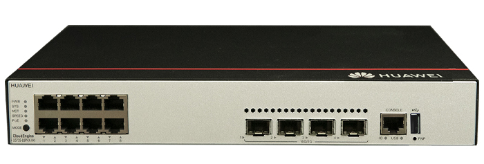
Figure 4-464 S5735-L8P4X-IA1 appearance

| 1 | Eight 10/100/1000BASE-T PoE+ ports | 2 | Four 10GE SFP+ ports |
| 3 | One console port | 4 | One USB port |
| 5 | One PNP buttonNOTICE:To restore the factory settings and reset the switch, hold down the button for at least 6 seconds.To reset the switch, press the button.Resetting the switch will cause service interruption. Exercise caution when you press the PNP button. | 6 | Ground screwNOTE:It is used with a ground cable. |
| 7 | AC socketNOTE:It is used with an AC power cable. | 8 | Jack for AC power cable locking strapNOTE:The AC power cable locking strap is not delivered with the switch. |
Ports
Table 4-1210 Ports on the S5735-L8P4X-IA1
| Port | Connector Type | Description | Available Components |
|---|---|---|---|
| 10/100/1000BASE-T PoE+ port | RJ45 | A 10/100/1000BASE-T Ethernet electrical port sends and receives service data at 10/100/1000 Mbit/s.The port supports the PoE function. | Ethernet cable |
| 10GE SFP+ optical port | SFP+ | A 10GE SFP+ Ethernet optical port supports auto-sensing to 1000 Mbit/s. It sends and receives service data at 1000 Mbit/s or 10 Gbit/s. | Industrial optical modules |
| Console port | RJ45 | The console port is connected to a console for on-site configuration. | Console cable |
| USB port | USB 2.0 Type A | The USB port can have a USB flash drive connected to upgrade the switch, or transfer configuration files or other files. The USB port can only connect to a USB flash drive that complies with USB 2.0.USB flash drives from different vendors differ in model compatibility and drivers. If a USB flash drive cannot be used, try to replace it with another one from a mainstream vendor. Switches support a maximum of 128 GB USB flash drives. | USB flash drive |
Indicators and Buttons
Figure 4-465 Indicators on the switch

Table 4-1211 Description of indicators on the switch
| No. | Indicator | Name | Color | Status | Description |
|---|---|---|---|---|---|
| 1 | PWR | Power module indicator | - | Off | The switch is powered off. |
| Green | Steady on | The system power supply is normal. | |||
| 2 | SYS | System status indicator | - | Off | The system is not running. |
| Green | Fast blinking | The system is starting. | |||
| Green | Steady on | During the system startup preparation phase, the SYS indicator is steady green, which lasts for a maximum of 30 seconds. | |||
| Green | Slow blinking | The system is running normally. | |||
| Red | Steady on | The system does not work normally after registration, or a fan alarm or a temperature alarm has been generated. | |||
| 3 | MST | Stack indicator | - | Off | If you are not changing the indicator mode (default): The switch is a standby or slave switch in a stack or the stacking function is not enabled on the switch.If you are changing the indicator mode: The stack mode is not selected. |
| Green | Steady on | The stack mode is selected. The switch is a standby or slave switch in a stack, and the service port indicators show the stack ID of the switch. | |||
| Green | Blinking | If you are not changing the indicator mode (default): The switch is the master switch in a stack or a standalone switch with the stacking function enabled.If you are changing the indicator mode: The stack mode is selected. The switch is the master switch in a stack or a standalone switch, and the service port indicators show the stack ID of the master switch. After 45 seconds, the service port indicators automatically restore to the status mode. | |||
| 4 | SPEED | Speed indicator | - | Off | The speed mode is not selected. |
| Green | Steady on | The speed mode is selected, and service port indicators show the speed of each port. | |||
| 5 | PoE | PoE indicator | - | Off | The PoE mode is not selected. |
| Green | Steady on | The PoE mode is selected, and service port indicators show the PoE status of each port. | |||
| 6 | MODE | Mode switch button | - | - | When you press this button once, the service port indicators change to the stack mode and show the stack ID of the local switch.When you press this button a second time, the service port indicators change to the speed mode and show the speed of each service port.When you press this button a third time, the service port indicators change to the PoE mode and show the PoE status of each service port.When you press this button a fourth time, the service port indicators restore to the default mode and show the connection status and link activity of each service port.If you do not press the MODE button within 45 seconds, the service port indicators restore to the default mode. In this case, the SPEED and PoE indicators are off.NOTE:Hold down the mode switch button for 6s and release it to start the web initial login mode. Either of the following situations will occur:If the switch has no configuration file, the system attempts to enter the web initial login mode. In this mode, the status of mode indicators is as follows:If the system enters the web initial login mode successfully, all mode indicators turn green and stay on for a maximum of 10 minutes.If the system fails to enter the initial login mode, all mode indicators fast blink for 10 seconds and then restore the default status.If the switch has a configuration file, the system cannot enter the web initial login mode. In this case, all mode indicators fast blink for 10s, and then return to the default states. |
| 7 | - | Service port indicator (one indicator for each port) | Arrowheads show the positions of ports. A down arrowhead indicates a port at the bottom, and an up arrowhead indicates a port at the top. | Meanings of service port indicators vary in different modes. For details, see Table 4-1212.NOTE:If a power failure occurs on a device's PCB board, indicators of the last four optical ports on the device's front panel blink green cyclically at an interval of 1 second, with each indicator illuminating for 0.25 seconds. | |
| 8 | ID | ID indicator | - | Off | The ID indicator is not used (default state). |
| Blue | Steady on | The indicator identifies the switch to maintain. The ID indicator can be turned on or off remotely to help field engineers find the switch to maintain. | |||
| 9 | USB | USB-based deployment indicator | - | Off | No USB flash drive is connected to the switch.The USB port is damaged.The indicator is damaged.The USB flash drive does not have any configuration file and cannot be used for deployment.The switch has been upgraded using the USB flash drive and is restarting. |
| Green | Steady on | A USB-based deployment has been completed. | |||
| Green | Fast blinking | The system is reading data from a USB flash drive. | |||
| Green | Slow blinking | The switch has copied all the required files and completed the file check. The USB flash drive can be removed from the switch. | |||
| Red | Fast blinking | An error has occurred when the system is executing the configuration file or reading data from the USB flash drive. | |||
| Display Mode | Color | Status | Description |
|---|---|---|---|
| Default mode | - | Off | The port is not connected or has been shut down. |
| Green | Steady on | A link has been established on the port. | |
| Green | Blinking | The port is sending or receiving data. | |
| MST stack mode | - | Off | Port indicators do not show the stack ID of the switch. |
| Green | Steady on | The switch is not the master switch in a stack.If the indicator of a port is steady on, the number of this port is the stack ID of the switch.If the indicators of ports 1 to 9 are steady on, the stack ID of the switch is 0. | |
| Green | Blinking | The switch is the master switch in a stack.If the indicator of a port is blinking, the number of this port is the stack ID of the switch.If the indicators of ports 1 to 9 are blinking, the stack ID of the switch is 0. | |
| Speed mode | - | Off | The port is not connected or has been shut down. |
| Green | Steady on | 10M/100M/1000M port: The port is operating at 10 Mbit/s or 100 Mbit/s.1000M/10GE port: The port is operating at 1000 Mbit/s. | |
| Green | Blinking | 10M/100M/1000M port: The port is operating at 1000 Mbit/s.1000M port: The port is operating at 1000 Mbit/s.1000M/10GE port: The port is operating at 10 Gbit/s. | |
| PoE mode | - | Off | The port is not providing power to a powered device (PD). |
| Green | Steady on | The port is providing power to a PD. | |
| Green | Blinking | The power of the PD connected to the port exceeds the power capacity of the port or the power threshold configured on the port. Alternatively, the PD does not comply with IEEE standards. |
Power Supply System
The switch has a built-in AC power module and does not support pluggable power modules. The built-in power module can provide 124 W PoE power, which ensures full PoE power on 8 ports in compliance with 802.3af or on 4 ports in compliance with 802.3at.
Heat Dissipation System
The switch has a built-in fan for forced air cooling. Air flows in from the left side and front panel, and exhausts from the right side.
When working properly at a normal temperature, the device meets the desktop-class noise requirements. However, the fan speed may be high and the noise may be loud during device startup.


This figure only shows the airflow direction and does not depict the actual device.
Technical Specifications
Table 4-1213 Technical specifications of the S5735-L8P4X-IA1
| Item | Specification |
|---|---|
| Dimensions without packaging (H x W x D) [mm(in.)] | Basic dimensions (excluding the parts protruding from the body): 43.6 mm x 300.0 mm x 220.0 mm (1.72 in. x 11.81 in. x 8.66 in.)Maximum dimensions (the depth is the distance from ports on the front panel to the parts protruding from the rear panel): 43.6 mm x 300.0 mm x 227.0 mm (1.72 in. x 11.81 in. x 8.94 in.) |
| Dimensions with packaging (H x W x D) [mm(in.)] | 110.0 mm x 435.0 mm x 360.0 mm (4.33 in. x 17.13 in. x 14.17 in.) |
| Chassis height [U] | 1 U |
| Chassis material | Metal |
| Weight without packaging [kg(lb)] | 2.23 kg (4.92 lb) |
| Weight with packaging [kg(lb)] | 3.04 kg (6.7 lb) |
| Typical power consumption [W] | 26.2 W |
| Typical heat dissipation [BTU/hour] | 89.40 BTU/hour |
| Maximum power consumption [W] | Without PoE: 33 WFull PoE load: 178 W (PoE: 124 W) |
| Maximum heat dissipation [BTU/hour] | Without PoE: 112.60Full PoE load: 607.35 |
| Static power consumption [W] | 18.7 W |
| MTBF [years] | 62.46 years |
| Availability | > 0.99999 |
| Noise at normal temperature (acoustic power) [dB(A)] | 42.2 dB(A) |
| Noise at normal temperature (acoustic pressure) [dB(A)] | 30.5 dB(A) |
| Number of card slots | 0 |
| Number of power slots | 0 |
| Number of fans modules | 1 |
| Redundant power supply | Not supported |
| Long-term operating temperature [°C(°F)] | –40°C to +65°C (–40°F to +149°F) at an altitude of 0–1800 m (0–5906 ft.)NOTE:–40°C to –30°C (–40°F to –22°F): Stable port performance can be achieved only when at least two Ethernet electrical ports go Up. |
| Short-term operating temperature [°C(°F)] | –40°C to +70°C (–40°F to +158°F) at an altitude of 0-1800 m (0-5906 ft.) |
| Restriction on the operating temperature variation rate [°C(°F)] | When the altitude is 1800-5000 m (5906-16404 ft.), the highest operating temperature reduces by 1°C (1.8°F) every time the altitude increases by 220 m (722 ft.).The device can work for a short period of time when the operating temperature is beyond the normal range, but the following conditions must be met:The operating temperature can exceed 65°C (149°F) for a maximum of 96 consecutive hours in a year.The total time when the operating temperature exceeds 65°C (149°F) in a year is less than or equal to 360 hours.The number of times the operating temperature exceeds 65°C (149°F) is less than or equal to 15 in one year.If any of the preceding conditions is not met, the device may be damaged or an unknown error may occur.The maximum transmission distance of an optical module used for short-term operation cannot exceed 10 km. |
| Storage temperature [°C(°F)] | –40°C to +75°C (–40°F to +167°F) |
| Long-term operating relative humidity [RH] | 5% RH to 95% RH, non-condensing |
| Long-term operating altitude [m(ft.)] | 0-5000 m (0-16404 ft.) |
| Storage altitude [m(ft.)] | 0-5000 m (0-16404 ft.) |
| Power supply mode | AC built-in |
| Rated input voltage [V] | AC input: 100 V AC to 240 V AC, 50/60 Hz |
| Input voltage range [V] | AC input: 90 V AC to 290 V AC, 45 Hz to 65 Hz |
| Maximum input current [A] | 3 A |
| Memory | 512 MB |
| Flash memory | 512 MB |
| Console port | RJ45 |
| Eth Management port | Not supported |
| USB | Supported |
| RTC | Not supported |
| RPS input | Not supported |
| Service port surge protection [kV] | Common mode: ±7 kV |
| Power supply surge protection [kV] | ±6 kV in differential mode, ±6 kV in common mode |
| Ingress protection level (dustproof/waterproof) | IP20 |
| Types of fans | Built-in |
| Heat dissipation mode | Heat dissipation with fan, intelligent fan speed adjustment |
| Airflow direction | Air intake from left and front, air exhaustion from right |
| PoE | Supported |
| Certification | EMC certificationSafety certificationManufacturing certification |